|
||||||||||||||||||||||||||||||||||||||||||||||||||||||||||||||
| ||||||||||||||||||||||||||||||||||||||||||||||||||||||||||||||
Modelling the river system1.Modelling OverviewA river system is generally modelled using two types of approaches
The Hydrologic modelling is applied on hydrographic basins where precipitation are transformed into discharges in rivers. Hydraulic modelling consists in routing discharges from upstream to downstream along the river reaches.  Hydrological processes are quite complex as rain or snow does not go directly into river channels, but follows conceptually different transfers along different processes before reaching the basin outlet. There are different ways of modelling these processes of water transfer from rain to discharges : hydrological models may be lumped (a basin is considered as a whole) or distributed (the basin is discretised into small (#1ha) connected unit elements where all processes are modelled and routed into each others). Usually, in operational hydrology lumped models are used, and this is the case in our project. Hydraulic models (or Hydrodynamic; HD) are more complex : they are based upon the hydrodynamic equations of water flows named St Venant equations. These equations are solved by linking unitary elements to others which make the description of the rivers, within which the water exchanges are driven by the physical laws. The unit elements may be 1D (one dimensional) or 2D (2 dimensional horizontal) An Hydraulic model is said to be closed when it is provided by limit conditions : This mean that all extremities that make the model need to have som input condition which drives its behaviour. Beside, all models need to have some initial condition or state from which it will evolve with the limit conditions which are applied. In our case we used branched 1D model (integration of sections perpendicular to the flow) with eventual secondary flows in the upper banks.
2.Conceptual model Of Maritza and TundjaBelow the river scheme of the Maritsa catchment is shown. This scheme has been modelled and calibrated in 2 sections: from Belovo to Plovdiv and from Plovdiv to the Turkish border. When the calibration of both parts was finished the models have been combined and validated as one model. Maritsa section 1
Maritsa section 2
Length is rounded off in km Additional cross-sections were used from the gauging stations (10). 
2.1 Conceptual model TundzhaBelow the river scheme of the Tundja catchment is shown. This scheme will be modelled and calibrated as a whole because there are not enough gauging stations available to divide the scheme in model sections.
Length is rounded off in km Additional cross-sections could be used from the JICA project (9) and from gauging stations (4).
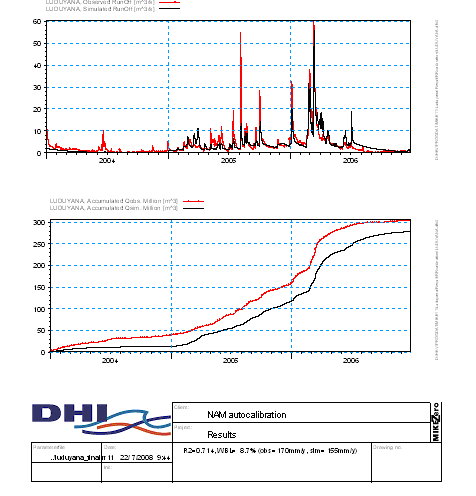
3. Model Set Up3.1 Hydrological Model Set upThe Hydrological Model used in our case is the NAM model provided by Mike11 software. NAM model is a continuous precipitation-runoff model of the deterministic, lumped, conceptual type. It includes simulation of snowmelt in different altitude zones within the catchment. NAM represents various components of the rainfall-runoff process by continuously accounting for the water content in four different and mutually interrelated storages. These storages are Snow, Surface, Root Zone and Ground Water Storages. Using rainfall, potential evaporation and temperature as input, the model simulates Snow accumulation and melting, interception, evapotranspiration, overland flow, groundwater recharge and baseflow. In case of using snowmelt component, NAM module needs additional snowmelt parameters. The model utilizes the temperature index model for the computation of daily snowmelt. The Snow melt module uses a temperature input time series, usually mean daily temperature. Users may choose the simple snowmelt or extended more sophisticated snowmelt module in the system. Each hydrological model of the system is first defined conceptually using the watershed separation into subbasins. The models are thus constructed from GIS basin and sub-basins zoning. Their initial definition (ie the first evaluation of parameters) before calibration is based upon the various elements available within the GIS : Surface and shape of the basin, land cover, soil properties, geological information, slopes and elevations, etc. The calibration of the hydrologic model consists in refining the parameters that make up each single model. For this we made use of historical observed data. By running the model with real observed data as input (rain, snow, temperature, evapotranspiration,..) and comparing its output with the observed discharges we optimise the various parameters in order to minimise the differences between output results and observed data on several measured sequences. The Mike 11 software provides semi automatic procedures in order to facilitate the calibration process which is rather long and tedious.
3.2 Hydraulic Model Set UpThe used model, Mike 11, is a one dimensional type hydraulic model: flows in reaches and overflows into floodplain where storage and flow are simulated, have a multidirectional though one dimensional formulation. Hydraulic models are constructed using true channel details, aggregated runoff coefficients, floodplain storage mechanisms, and significant structures such as bridges, weirs, levees, terraces, reclamations, pond bunds… A detailed topography of the flood plain up to the break of slope to the terraces or hills is thus required in order to build the hydraulic system to be modelled. Hydraulic modelling is based on nodes linked into a topological network. For nodes linked together in the main channel and the immediate left and right side flood plain, an implicit scheme of resolution of St Venant set of differential equations is used. For the nodes within the flood plain associated with topographic structures as levees, roads, railway tracks, which delimited retention zones, St Venant equations are also solved, and additionally, overflows can be modelled using spillway discharge equations. Because of the detailed topographic description used, and because water height is the main controlling variable to model the flows in the flood plain structures, the topographic data have to be accurate enough for the model to be effective in its forecasts. A 10 cm overall accuracy in elevation, for the topographic structure is generally required for these models. Depending on the channel and embankments topographic variations, the cross section spacing may vary from 2-3 km to as low as 200 m. When the flood plain and river channel slope is rather flat, as it is the case in the downstream Maritza and Tundja basins, Hydraulic models are very sensitive to topographic inaccuracies. This mean that water height divergences (which may result from a poorly accurate topographic survey) between real data and simulated data will propagate numerically downstream and upstream, leading to an overall poor result. The main limitation for these hydraulic models is thus the quality of the topographic data used to construct their topology. The other points (solver methods, implicit or explicit schemes…) hydraulic coefficient values, while important in the calibration process and for computation fiability and performances, are less critical for accurateness issues thanks to the know how gained today on these tools. The Hydraulic model development contains the following steps:
Note that, although the calibration and validation of the models can only start when all data is collected, analysed and processed, the steps before the calibration do not depend on one another and can be executed separately. Mike 11 software provides semi automatic procedures in order to facilitate the calibration process of the HD model.  |
||||||||||||||||||||||||||||||||||||||||||||||||||||||||||||||
|
||||||||||||||||||||||||||||||||||||||||||||||||||||||||||||||
 Our general
model of Maritza and Tundja is thus made of several hydrologic models
which provide discharges from rain or snow melting and of several
Hydraulic models (main river and some tributaries) all linked and
coupled together.
Our general
model of Maritza and Tundja is thus made of several hydrologic models
which provide discharges from rain or snow melting and of several
Hydraulic models (main river and some tributaries) all linked and
coupled together.